Case Study: X-Ray Powder Diffraction (XRPD) Analysis
XRPD is a powerful, non-destructive and rapid technique used for the analysis of a wide range of materials (of size from 1 µm to 100 mm). This includes materials such as metals, polymers, catalysts, plastics, pharmaceuticals and more.
Key Features
It is an important technique for investigating and characterizing crystalline materials in the QC and R&D Laboratories
The most effective qualitative method for the identification of a phase purity of an unknown bulk composition
Only minimal sample preparation is required
Straightforward data interpretation
Instrument Details
X-ray Tube
The main source of X-Rays
Incident-Beam Optics
Condition the X-ray beam before it hits the sample
Goniometer
A platform that holds and moves the sample, optics, and detector.
Sample Holder
Holds the sample in place and rotates it, if required.
Air Scatter
Controls the size of the viewed diffracting sample surface, so as to improve diffraction resolution and minimize cross-contamination.
Receiving-side Optics
Condition the X-ray beam after it has encountered the sample
Detector
Counts the number of X-Rays scattered by the sample
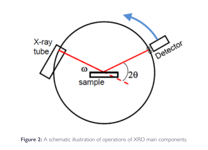
Operation of an XRPD
X-rays are generated in a cathode ray tube. By heating a filament to produce electrons, they are accelerated toward a particular target by applying voltage and bombarding the target material (Cu, λ = 1.54 wavelength) with electrons.
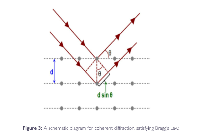
The generated X-rays are directed towards the sample while the diffracted rays are collected by the detector (See Figures 2 & 3).
A key component of all diffraction is the angle between the incident and diffracted rays (2θ). A typical powder patterns data is collected at 2θ from ~5° to 70°, which are the angles that are present in the X-ray scan.
A detector records and processes this X-ray signal and converts the signal to a count rate which is then sent forward to record its output, to a printer or a computer monitor.
Interpretation
The peak intensities in the diffractogram are determined by the distribution of atoms within the lattice. As a result, the X-ray diffraction pattern is the fingerprint of periodic atomic arrangements in a given sample
Even with the same chemical composition, phases can have drastically different diffraction patterns
The position and relative intensity of a series of peaks can be used to match experimental data to reference data in a database
The relative intensity and position of a series of peaks can be used to match with experimental data in order to reference data in a database
References
USP <941> : X-ray diffraction USP monograph, Current Edition
A – Identification of Polymorphic Forms
Problem Statement
Getting different polymorphic forms of material after working up the reaction mixture is possible.
Impact
Different polymorphs can affect the solubility, dissolution rate, bioavailability and physical stability of the drug substance.
Identification Technique
XRPD is the best technique to identify different polymorphic forms in the reaction mixture [USP <941>]

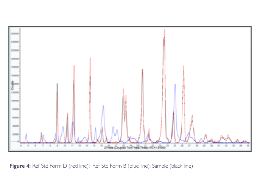
Results:
-
A comparison of the sample diffractogram with Ref. Std. diffractograms confirmed that the sample is present in Form D (For more details, see Figure 4)
-
The agreement in the 2θ-diffraction angles between the sample and the Ref Std is within 0.2°
-
Due to preferred orientation effects, Peak relative intensities between the sample and Ref Std may vary considerably
B – In-Process Production Support
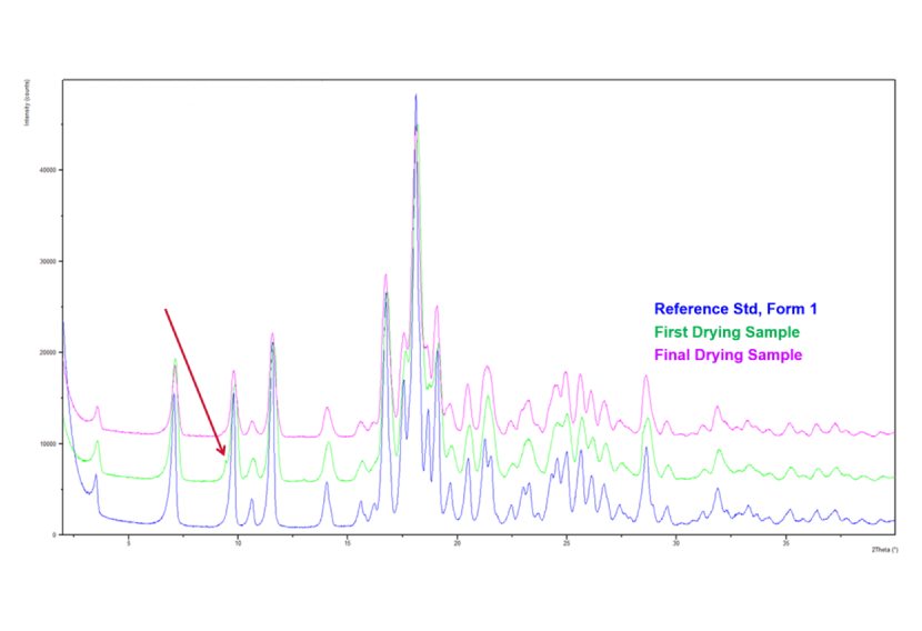
XRPD analysis can be used for production support to confirm the correct Form is being produced.
Conversion from Form 2 to preferred Form 1 occurs during drying; XRPD testing was performed as an “In-Process” test to confirm complete conversion to Form 1.
The red arrow points out to undesired Form 2; present in the First Drying Sample and not present in the Final Drying Sample.